|
|
|
|
|
|
|
|
 ARRESTERS (Model # : ART SERIES)
 |
| |
|
 Description
 |
| |
LOW INSERTION LOSS & VSWR
AVAILABLE INTERNAL CD
BIAS PATH
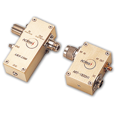
This
unit is specially designed for
DC injection onto main RF signal
line. DC clamping circuit is added
to protect system from surge or
lightning. Various type arresters
are available upon request. |
|
|
| |
 Specifications
 |
| |
Mode
No.
|
ART-800
|
ART-1500
|
ART-1800H1
|
ART-1800U
|
AEP-2500 |
| Range[MHz] |
800 ~ 900 MHz |
1450 ~ 2000 MHz |
1700 ~ 2000 MHz |
1450 ~ 2000 MHz |
DC ~ 250 MHz |
Operating Voltage/
Current or Power |
+15Vdc/2.5A |
+15Vdc/2.5A |
>+27Vdc/20A |
+15Vdc/2.5A |
25 W max. |
| Operating Temperature |
-30 ~ +60 °C |
-30 ~ +60 °C |
-30 ~ +70 °C |
-10 ~ +65 °C |
-45 ~ +85°C |
| Insertion Loss |
0.4 dB max. |
0.2 dB max. |
- |
0.15 dB max. |
0.45 dB max. |
| VSWR |
1.15:1max. |
>1.15:1max. |
1.20:1max. |
1.15:1max. |
1.30:1max. |
| Throughput Energy |
6KV/3KA 1.2/50us
1.2/50us
OCV, 8/20us
SCC
waveform |
6KV/3KA 1.2/50us
1.2/50us
OCV, 8/20us
SCC
waveform |
- |
6KV/3KA 1.2/50us
1.2/50us
OCV, 8/20us
SCC
waveform |
700V(Dynamic)
90V(Static) |
| Connector Type |
Type-N(F) |
Type-N(F) |
Type-N(F)/
SMA(F) |
Type-N(F) |
Type-N(F) |
Dimension(W×L×H)
[mm(inch)] |
93x38x33
(3.66x1.5x1.3) |
65x45x33
(2.56x1.77x1.30) |
93.2x38.2x32.6
(3.66x1.5x1.3) |
|
|
| |
|
|
|
|